
Introduction
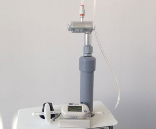
You can use the TSI 440 flowmeter or a single rotameter to measure the flow rate of your particle monitor.
To understand how often you should perform this service activity, click here.
-
-
Enter service mode so any fluctuations in the data caused from this activity can be excluded from air quality reports.
-
-
-
The flow rate of the particle monitor must be 2.0 LPM ± 0.05 (between 1.95 and 2.05 LPM).
-
A constant 2.0 LPM flow is essential to ensure the sharp cut cyclone is separating out the correct particle size for measurement, eg. PM10 or PM2.5.
-
-
-
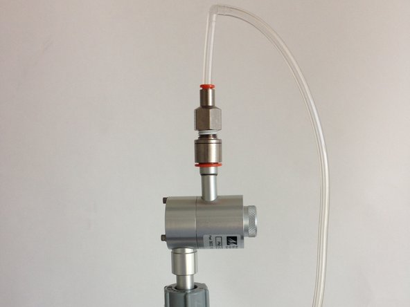
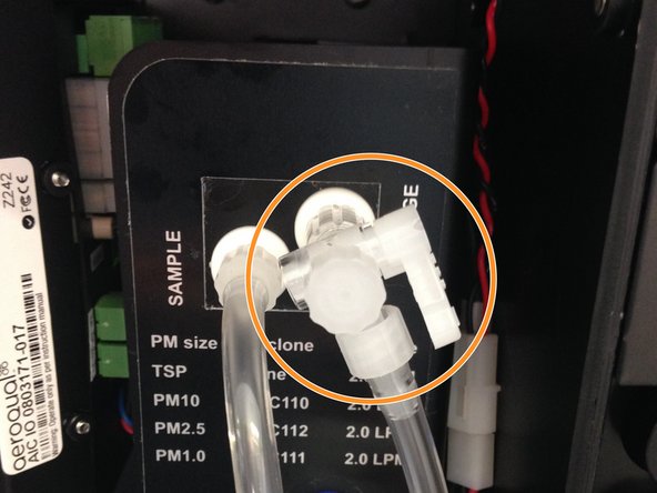
Remove the TSP head from the top of the sharp cut cyclone and attach the flow adaptor on your flow assembly.
-
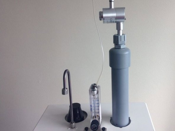
Attach the flow assembly to a 0-2.5 LPM volumetric flow meter.
-
If using the R8 flowmeter, connect the assembly to the top port of the flowmeter (negative flow).
-
Ensure the flowmeter is on a steady surface before reading the flow rate.
-
-
-
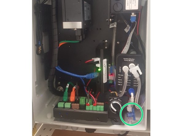
Adjust the sample flow by pulling the adjustment knob outwards, turning the knob to increase/decrease flow, and pushing the knob back in to lock when desired flow has been reached.
-
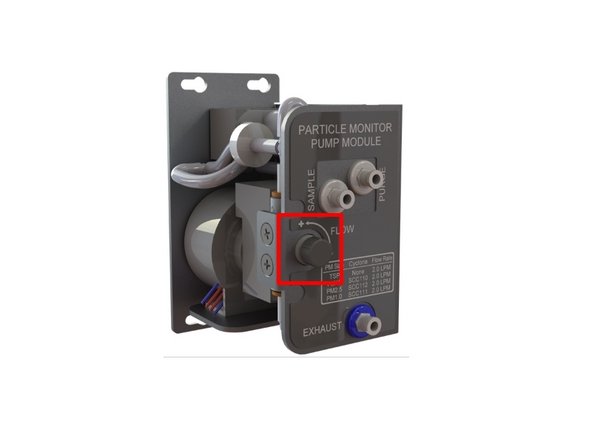
If the flow isn't correct, adjust the sample flow valve which is located on the face plate of the pump module, until the flow reads 2.0 LPM ± 0.05 (between 1.95 and 2.05 LPM).
-
To adjust the flow on older monitors, fully close the purge valve by pushing the valve handle towards the pump module. Adjust the sample flow valve, located at the bottom of the enclosure under the PDI cover, until the flow reads 2.2 LPM. Then slowly re-open the purge valve until the flow reads 2.0 LPM ± 0.05 (between 1.95 and 2.05 LPM).
-
If you can't reach the required flow rate, there may be a leak, the sample and purge filters may be dirty, or the pump may need replacing.
-


For further support, contact Technical Support.
For further support, contact Technical Support.
Cancel: I did not complete this guide.
3 other people completed this guide.
